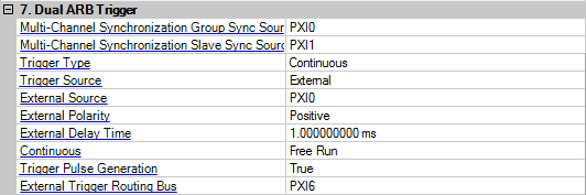
The image below shows a composite set of the Dual ARB Trigger parameters when connected to an M9381A PXIe VSG.
Choice: PXI0 | PXI1 | PXI2 | PXI3 | PXI4 | PXI5 | PXI6 | PXI7
Default: PXI0
Specify the backplane bus that master VSG used to send Group Synchronization Signal to trigger slave VSGs. And the slave VSGs wait on this bus line.
Choice: PXI0 | PXI1 | PXI2 | PXI3 | PXI4 | PXI5 | PXI6 | PXI7
Specify the backplane bus that slave VSG used to send Slave Synchronization Signal to trigger master VSG for handshaking.
Choice: Continuous | Single | Gated | Segment Advance
Choice (M9381A): Continuous | Single
Default: Continuous
This cell selects the triggering mode.
Continuous – selects the continuous triggering mode, which enables the signal generator to repeat the modulating signal indefinitely until you turn off the modulation format, change triggers, or select another waveform.
Single – sets up a waveform to play once after receiving a trigger. See Single to configure the waveform's response to triggers.
Gated – sets the signal generator to the gated trigger mode, which causes the waveform (modulating signal) to repeatedly start and stop in response to an externally applied trigger signal. To use the gated trigger mode, you must also select .
Segment Advance – controls the way the signal generator plays segments within a sequence. This includes determining whether a segment plays once or continuously, and when the sequence advances to the next segment. See Segment Advance.
Choice: Trigger Key | External | Bus
Choice (M9381A): External | Bus
Default: External
This cell adjusts the trigger source applied to the or connectors.
Trigger Key – selects the front panel hardkey as the trigger source. After making this selection, press the hardkey to trigger a waveform.
External – causes a waveform to trigger from an externally supplied trigger signal.
Bus – enables a command sent through the GPIB, LAN or AUXILIARY IO (RS-232) input connector to trigger a waveform.
Choice: Pattern Trigger In 1 | Trigger Pattern In 2
Choice (M9381A): TRIG1 | PXI0 | PXI1 | PXI2 | PXI3 | PXI4 | PXI5 | PXI6 | PXI7
Default: Pattern Trigger In 1
This cell selects the rear-panel input for the external trigger signal. must be selected as the trigger source.
Pattern Trigger In 1 – selects the PATTERN TRIG IN rear-panel BNC connector
Pattern Trigger In 2 – selects the AUXILIARY I/O rear panel connector
For the M9381A PXIe VSG, double-click or use the drop-down menu to select the front-panel input for the external trigger signal. must be selected as the trigger source.
– selects the Trig 1 front-panel SMA connector as the external trigger input for the M9381A PXIe VSG
– selects the backplane bus signal for the M9381A PXIe VSG
Choice: Positive | Negative
Default: Negative
This toggles the polarity of the TTL signal at the rear panel TRIGGER OUT connector.
Positive – the trigger out signal is asserted high (+ 5.0 V) at the start of the swept-sine modulation sweep and low (0 V) when the sweep ends.
Negative – reverses the polarity, so that the trigger out signal is low (0.0 V) at the start of the swept-sine modulation sweep and high (+ 5.0 V) when the sweep ends.
Choice: On | Off
Default: Off
This cell turns the external trigger delay off or on. The selection is active only after selecting as the trigger source.
Range:
N5182A: 8 ns to 30 s, in 8 ns steps
All other models: 10 ns to 40 s, in 10 ns steps
Default:
8 ns or 10 ns
This cell sets the amount of time to delay the signal generator's response to an external trigger, in 10 ns steps. The delay is a path (time) delay between the time the signal generator receives the trigger and when it responds to the trigger.
Choice: Free Run | Trigger & Run | Reset & Run
Choice (M9381A): Free Run| Trigger & Run
Default: Free Run for 802.11a/b/g/j/p, 802.11n MxN, and 802.11n 1ARB with 2 SG system; Trigger & Run for 802.11n Mx2, Mx3, and Mx4 systems.
This cell selects the waveform's response to triggers when Continuous is the trigger mode (continuous waveform transmission.)
Free Run – immediately triggers when you turn the format on.
Trigger & Run – waits for and starts on the first trigger; ignores subsequent triggers.
Reset & Run – waits for and starts on the first trigger; resets and plays on a subsequent trigger.
Choice: Buffered Trigger | No Retrigger | Restart on Trigger
Default: Restart on Trigger for 802.11a/b/g/j/p, 802.11n MxN, and 802.11n 1ARB with 2 SG system; No Retrigger for 802.11n Mx2, Mx3, and Mx4 systems.
This cell configures the waveform's response to triggers while using the single trigger mode. The response selections determine whether the waveform accepts a trigger during playback, and if it does, how it responds to that trigger.
No Retrigger – causes the waveform to ignore the triggers during playback.
Buffered Trigger – causes a waveform to accept a trigger during payback and to restart after the current play finishes.
Restart on Trigger – causes a waveform to accept a trigger during playback and to restart immediately after receiving a trigger.
Choice: Single | Continuous
Default: Continuous
This cell configures how play moves from segment to segment within a waveform sequence.
Single – causes a segment to play once and wait for a trigger before the sequence advances to the next segment.
Continuous – causes a segment to play continuously until receiving another trigger. Upon receiving the trigger, the sequence advances to the next segment, which then plays continuously.
Choice: Active High | Active Low
Default: Active High
Sets the signal generator to the gated trigger mode, which causes the waveform (modulating signal) to repeatedly start and stop in response to an externally applied trigger signal. To use the gated trigger mode, you must also select External.
Sets the trigger active state for the gated trigger mode.
Gate = Active High
Trigger Signal State = High
Waveform file plays.
Gate = Active High
Trigger Signal State = Low
Waveform file stops playing.
Gate = Active Low
Trigger Signal State = High
Waveform file stops playing.
Gate = Active Low
Trigger Signal State = Low
Waveform file plays.
Choice: On | Off
Default:On
Double-click the cell or use the drop-down menu to select a trigger pulse generation state. This enables a trigger pulse generation after waveform downloading finished.
To enable and perform the function, Trigger Source should be set to External and Continuous should be set Trigger Run.
Choice: PXI0 | PXI1 | PXI2 | PXI3 | PXI4 | PXI5 | PXI6 | PXI7
Default: PXI6